When preparing to engrave on a new product or material for the first time, the operator should dedicate the first product or test piece of material to running a laser power grid.

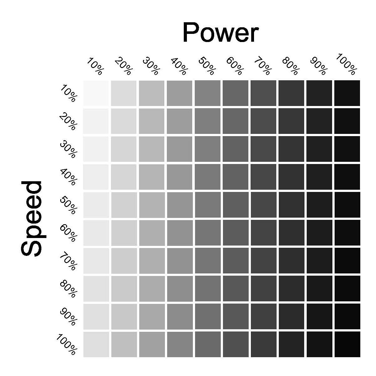
A laser power grid typically consists of a matrix of engraved squares arranged in a grid pattern. The grid pattern is best arranged as an XY coordinate-style table. The X-axis (left to right) represents an increase in laser power. The Y-axis (up and down) represents an increase in laser speed. At the origin point of the table (top left), the speed/power settings are at their least intense (slowest speed/lightest power). At the opposite end of the origin point (bottom right) of the grid, the speed/power settings are the most intense (highest speed/highest power). All other engraved squares within the matrix show all speed/power combinations in between the two extremes. The top right of the matrix will likely show the deepest engraving (highest power/slowest speed), and the bottom left of the matrix will likely show a shallow engraving depth (lowest power/highest speed).
The increments between power/speed settings are typically 10% increments; however, these can be adjusted to a lower increment such as 5% or even 1% if the material or product requires extremely precise settings.
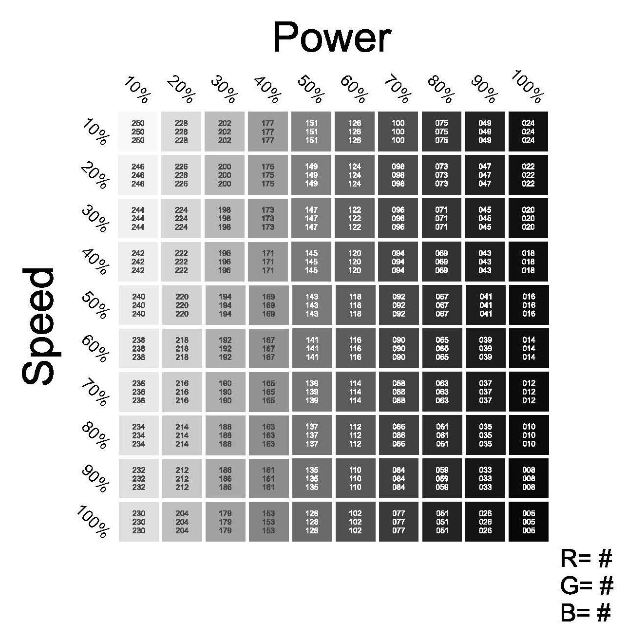
The process of running a power grid can be somewhat automated if the laser is equipped with a color mapping feature. When using color mapping, each engraved square uses the RGB color values of that individual square to assign a power/speed setting for that square.

Consult the user manual of your laser for more details on the use of color mapping features.
By running a laser power grid, the laser will show you exactly what setting combination or range of setting combinations work best on that particular product or material.


